


As we saw in part-1 of this article, high availability of mission critical systems translates to improved security and redundant boot mechanisms ensures high availability of embedded systems.
Redundant boot mechanism – alternatives
Once a design decision is made to include redundant boot mechanism, there are 2 ways in which it could be implemented.
The first (and straightforward) way is to have a replica of the normal bootloader in the redundant boot device. Upon detecting failure of normal boot, redundant boot is initiated. Typically, the detection of normal boot failure and initiation of redundant boot process are performed autonomously by the Boot ROM of the silicon vendor, that may be transparent to system designers. This provides seamless redundant boot up, where the failure of normal boot remains hidden to the end user, therefore no manual intervention is required. Having a backup bootable image allows the system to recover from boot failures using the last well-known configuration. However, the trade-off is that the redundant boot device would need equal amount of memory as the normal boot device. This would necessitate a higher specification of memory components in the board design, potentially impacting the unit cost.
Whereas in a memory constrained environment which is typically the case for many embedded systems, redundant boot would have limited and specialized functionality. The objective is not necessarily to completely mimic the normal boot functionality, but to provide a minimalistic way of redundancy to recover from boot failures in the field. This could consist of a redundant bootloader that performs only a specialized operation, typically combined with minimal manual intervention, for recovering from the boot failure for improving system reliability.
A typical method could consist of prompting the end user upon detecting boot failure, to insert an SD-Card or USB drive into the device, that contains a copy of the normal boot image, load the boot image from there and boot up. This way, the device can be recovered in the field to continue providing its designated mission critical function. Despite the manual intervention involved, it offloads the larger system memory requirement to external media. However, using such removable media would in turn necessitate protection of the ports and encryption of the bootable image file, and authentication and integrity checks while loading the image from external media.
In either of the above cases, the redundant boot device is typically some kind of low speed SPI Flash, which would require copying over the bootable image to the main memory (RAM) first, before it can be executed. This is unlike the normal boot device which typically uses XIP (execute-in-place) Flash memory.
Redundant boot design and validation
The various stages involved in implementing and testing the redundant boot mechanism are as follows:
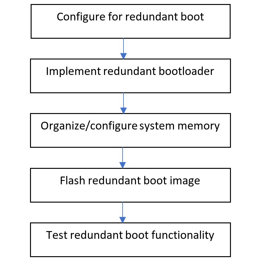
1. Configure microcontroller for redundant boot
In order to implement redundant boot, the first step is to configure the microcontroller for redundant boot. On many microcontrollers, this is typically performed by burning the relevant One-Time Programmable (OTP) e-Fuses. Additional parameters like the selection of the peripheral connected to the designated redundant boot device (usually SPI based Flash device) and the speed of operation of the Flash memory used for redundant boot are also configured by burning the relevant e-Fuses.
2. Implement redundant bootloader functionality
The core functionality of the redundant bootloader is developed using the same IDE/compiler recommended of the silicon vendor.
3. Organize and configure system memory
Once compiled and linked, the bootable image should have the required header information that will permit the loader (often referred to as Boot ROM) to parse the image file at runtime and load it to the appropriate addresses in memory. The program image may consist of multiple memory sections, like one section for text, another for uninitialized data, stack, heap etc. and are configured as per vendor recommendations.
In each memory section, the Load Memory Address (LMA) represents the address where the section will be stored in the redundant boot Flash, and the Virtual Memory Address (VMA) represents the address where that particular section will be copied in the main memory. The LMA and VMA need to be specified in the image header, that starts with the Image Vector Table (IVT) which maps to different start addresses for specific peripherals, like FlexSPI-NOR Flash, LPSPI-NOR Flash, NAND Flash etc. Depending on the part number, the redundant bootable image could be loaded to on-chip RAM which is closely coupled memory, that is fast but of lower size/capacity.
Alternatively, the image could be loaded to external SD-RAM, that is slow but has larger size/capacity. In the case of the latter, the initial device configuration of the external SD-RAM chip should have been performed prior to the loading process. This is typically taken handled by the boot image header design, from which the Boot ROM reads off the relevant device configuration information and sends the corresponding SD-RAM primitive commands to correctly configure its operation.
4. Flash the redundant boot image
The redundant boot image needs to be flashed into the redundant boot device as per the microcontroller’s documentation. This could be done either using the IDE, or by a standalone utility provided by the silicon vendor. Post-flashing validation check is mandatory to make sure that the CRC of the image written to the redundant boot device (destination) matches the bootable image file on the host (source).
5. Test redundant boot functionality
Finally, triggering redundant boot can be performed by simulating failure of the normal boot device. This can be done in several ways, one of which is to simply erase the normal bootable image. This would permit functional testing of the redundant bootloader’s actual functionality, that could include manual steps of plugging in SD-Card or USB drive with the encrypted normal bootable image.
Conclusion
Post implementation of redundant boot mechanism, system reliability metrics could be derived partly from pre-launch stress tests, from both non-destructive means like artificially corrupted normal bootable images, as well as from limited destructive tests, like physical/electrical damage to normal boot device. The metrics could also be partly derived from field failure data during the initial pilot deployments, with the help of low-level logs of boot failures and user assisted recovery.
Therefore, redundant boot for embedded systems is one of the mechanisms that improves system availability in the event of boot failure in the field, thereby improving the security of mission critical applications.